This article is about aircraft landing gear. For semitrailer landing gear, see semitrailer. For the Devin the Dude album, see Landing Gear.

Landing gear is the undercarriage of an aircraft or spacecraft that is used for taxiing, takeoff or landing. For aircraft, it is generally needed for all three of these. It was also formerly called alighting gear by some manufacturers, such as the Glenn L. Martin Company. For aircraft, Stinton makes the terminology distinction undercarriage (British) = landing gear (US).
For aircraft, the landing gear supports the craft when it is not flying, allowing it to take off, land, and taxi without damage. Wheeled landing gear is the most common, with skis or floats needed to operate from snow/ice/water and skids for vertical operation on land. Retractable undercarriages fold away during flight, which reduces drag, allowing for faster airspeeds. Landing gear must be strong enough to support the aircraft and its design affects the weight, balance and performance. It often comprises three wheels, or wheel-sets, giving a tripod effect.
Some unusual landing gear have been evaluated experimentally. These include: no landing gear (to save weight), made possible by operating from a catapult cradle and flexible landing deck: air cushion (to enable operation over a wide range of ground obstacles and water/snow/ice); tracked (to reduce runway loading).
For launch vehicles and spacecraft landers, the landing gear usually only supports the vehicle on landing and during subsequent surface movement, and is not used for takeoff.
Given their varied designs and applications, there exist dozens of specialized landing gear manufacturers. The three largest are Safran Landing Systems, Collins Aerospace (part of Raytheon Technologies) and Héroux-Devtek.
Aircraft
| This section needs additional citations for verification. Please help improve this article by adding citations to reliable sources in this section. Unsourced material may be challenged and removed. Find sources: "Landing gear" – news · newspapers · books · scholar · JSTOR (April 2018) (Learn how and when to remove this message) |
The landing gear represents 2.5 to 5% of the maximum takeoff weight (MTOW) and 1.5 to 1.75% of the aircraft cost, but 20% of the airframe direct maintenance cost. A suitably-designed wheel can support 30 t (66,000 lb), tolerate a ground speed of 300 km/h and roll a distance of 500,000 km (310,000 mi) ; it has a 20,000 hours time between overhaul and a 60,000 hours or 20 year life time.
Gear arrangements
- Airplanes
-
Conventional/taildragger Piper Cub
-
 Tricycle Cessna 152
-
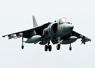 Bicycle AV-8B Harrier
-
 Quadricycle Fairchild XC-120 Packplane
Wheeled undercarriages normally come in two types:
- Conventional landing gear or "taildragger", where there are two main wheels towards the front of the aircraft and a single, much smaller, wheel or skid at the rear. The same helicopter arrangement is called tricycle tailwheel.
- Tricycle landing gear, where there are two main wheels (or wheel assemblies) under the wings and a third smaller wheel in the nose. PZL.37 Łoś Was the first bomber aircraft with twin wheels on a single shock absorber. The same helicopter arrangement is called tricycle nosewheel.
The taildragger arrangement was common during the early propeller era, as it allows more room for propeller clearance. Most modern aircraft have tricycle undercarriages. Taildraggers are considered harder to land and take off (because the arrangement is usually unstable, that is, a small deviation from straight-line travel will tend to increase rather than correct itself), and usually require special pilot training. A small tail wheel or skid/bumper may be added to a tricycle undercarriage to prevent damage to the underside of the fuselage if over-rotation occurs on take-off leading to a tail strike. Aircraft with tail-strike protection include the B-29 Superfortress, Boeing 727 trijet and Concorde. Some aircraft with retractable conventional landing gear have a fixed tailwheel. Hoerner estimated the drag of the Bf 109 fixed tailwheel and compared it with that of other protrusions such as the pilot's canopy.
A third arrangement (known as tandem or bicycle) has the main and nose gear located fore and aft of the center of gravity (CG) under the fuselage with outriggers on the wings. This is used when there is no convenient location on either side of the fuselage to attach the main undercarriage or to store it when retracted. Examples include the Lockheed U-2 spy plane and the Harrier jump jet. The Boeing B-52 uses a similar arrangement, except that the fore and aft gears each have two twin-wheel units side by side.
Quadricycle gear is similar to bicycle but with two sets of wheels displaced laterally in the fore and aft positions. Raymer classifies the B-52 gear as quadricycle. The experimental Fairchild XC-120 Packplane had quadricycle gear located in the engine nacelles to allow unrestricted access beneath the fuselage for attaching a large freight container.
Helicopters use skids, pontoons or wheels depending on their size and role.
- Helicopters
-
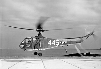 Tricycle tailwheel Sikorsky R-4
-
 Tricycle nosewheel Sikorsky CH-54
-
 Quadricycle Boeing CH-47 Chinook
-
 Skided Robinson R44
Retractable gear
To decrease drag in flight, undercarriages retract into the wings and/or fuselage with wheels flush with the surrounding surface, or concealed behind flush-mounted doors; this is called retractable gear. If the wheels do not retract completely but protrude partially exposed to the airstream, it is called a semi-retractable gear.
Most retractable gear is hydraulically operated, though some is electrically operated or even manually operated on very light aircraft. The landing gear is stowed in a compartment called a wheel well.
Pilots confirming that their landing gear is down and locked refer to "three greens" or "three in the green.", a reference to the electrical indicator lights (or painted panels of mechanical indicator units) from the nosewheel/tailwheel and the two main gears. Blinking green lights or red lights indicate the gear is in transit and neither up and locked or down and locked. When the gear is fully stowed up with the up-locks secure, the lights often extinguish to follow the dark cockpit philosophy; some airplanes have gear up indicator lights.
Redundant systems are used to operate the landing gear and redundant main gear legs may also be provided so the aircraft can be landed in a satisfactory manner in a range of failure scenarios. The Boeing 747 was given four separate and independent hydraulic systems (when previous airliners had two) and four main landing gear posts (when previous airliners had two). Safe landing would be possible if two main gear legs were torn off provided they were on opposite sides of the fuselage. In the case of power failure in a light aircraft, an emergency extension system is always available. This may be a manually operated crank or pump, or a mechanical free-fall mechanism which disengages the uplocks and allows the landing gear to fall under gravity.
-
 Retractable landing gear animation
-
Narrowbody aircraft have twin-wheel main landing gear legs.
-
 Widebody aircraft main legs have multiple-axle bogies.
-
High-wing cargo aircraft often have compartments similar to sponsons for the main gear.
- Video of Lancaster landing gear extension and retraction, ex-situ
Shock absorbers
Aircraft landing gear includes wheels equipped with solid shock absorbers on light planes, and air/oil oleo struts on larger aircraft.
-
Oleo strut (pressurized gas or oil) with torque links
-
Oleo strut with trailing link
-
Rubber discs in compression with trailing link of a Mooney M20
-
Simple spring steel bar, used on many light aircraft
-
Simple steel tube
Large aircraft

As aircraft weights have increased more wheels have been added and runway thickness has increased to keep within the runway loading limit. The Zeppelin-Staaken R.VI, a large German World War I long-range bomber of 1916, used eighteen wheels for its undercarriage, split between two wheels on its nose gear struts, and sixteen wheels on its main gear units—split into four side-by-side quartets each, two quartets of wheels per side—under each tandem engine nacelle, to support its loaded weight of almost 12 t (26,000 lb).
Multiple "tandem wheels" on an aircraft—particularly for cargo aircraft, mounted to the fuselage lower sides as retractable main gear units on modern designs—were first seen during World War II, on the experimental German Arado Ar 232 cargo aircraft, which used a row of eleven "twinned" fixed wheel sets directly under the fuselage centerline to handle heavier loads while on the ground. Many of today's large cargo aircraft use this arrangement for their retractable main gear setups, usually mounted on the lower corners of the central fuselage structure.
The prototype Convair XB-36 had most of its weight on two main wheels, which needed runways at least 22 in (56 cm) thick. Production aircraft used two four-wheel bogies, allowing the aircraft to use any airfield suitable for a B-29.
A relatively light Lockheed JetStar business jet, with four wheels supporting 44,000 lb (20 t), needed a 10 in (25 cm) thick flexible asphalt pavement. The 210,000 lb (95 t) Boeing 727-200 with four tires on two legs main landing gears required a 20 in (51 cm) thick pavement. The thickness rose to 25 in (64 cm) for a McDonnell Douglas DC-10-10 with 443,000 lb (201 t) supported on eight wheels on two legs. The heavier, 558,000 lb (253 t), DC-10-30/40 were able to operate from the same thickness pavements with a third main leg for ten wheels, like the first Boeing 747-100, weighing 700,000 lb (320 t) on four legs and 16 wheels. The similar-weight Lockheed C-5, with 24 wheels, needs an 18 in (46 cm) pavement.
The twin-wheel unit on the fuselage centerline of the McDonnell Douglas DC-10-30/40 was retained on the MD-11 airliner and the same configuration was used on the initial 275 t (606,000 lb) Airbus A340-200/300, which evolved in a complete four-wheel undercarriage bogie for the heavier 380 t (840,000 lb) Airbus A340-500/-600. The up to 775,000 lb (352 t) Boeing 777 has twelve main wheels on two three-axles bogies, like the later Airbus A350.
The 575 t (1,268,000 lb) Airbus A380 has a four-wheel bogie under each wing with two sets of six-wheel bogies under the fuselage. The 640 t (1,410,000 lb) Antonov An-225, the largest cargo aircraft, had 4 wheels on the twin-strut nose gear units like the smaller Antonov An-124, and 28 main gear wheels.

The 97 t (214,000 lb) A321neo has a twin-wheel main gear inflated to 15.7 bar (228 psi), while the 280 t (620,000 lb) A350-900 has a four-wheel main gear inflated to 17.1 bar (248 psi).
-
 The A340-600 has an additional main undercarriage on the fuselage belly.
-
 Wing and fuselage undercarriages on a Boeing 747-400, shortly before landing
-
 The 20-wheeled main undercarriage of an Airbus A380
-
 Main landing gear of the Antonov An-225 Mriya
STOL aircraft
STOL aircraft have a higher sink-rate requirement if a carrier-type, no-flare landing technique has to be adopted to reduce touchdown scatter. For example, the Saab 37 Viggen, with landing gear designed for a 5m/sec impact, could use a carrier-type landing and HUD to reduce its scatter from 300 m to 100m.
The de Havilland Canada DHC-4 Caribou used long-stroke legs to land from a steep approach with no float.
Operation from water
Main article: SeaplaneA flying boat has a lower fuselage with the shape of a boat hull giving it buoyancy. Wing-mounted floats or stubby wing-like sponsons are added for stability. Sponsons are attached to the lower sides of the fuselage.
A floatplane has two or three streamlined floats. Amphibious floats have retractable wheels for land operation.
An amphibious aircraft or amphibian usually has two distinct landing gears, namely a "boat" hull/floats and retractable wheels, which allow it to operate from land or water.
Beaching gear is detachable wheeled landing gear that allows a non-amphibious floatplane or flying boat to be maneuvered on land. It is used for aircraft maintenance and storage and is either carried in the aircraft or kept at a slipway. Beaching gear may consist of individual detachable wheels or a cradle that supports the entire aircraft. In the former case, the beaching gear is manually attached or detached with the aircraft in the water; in the latter case, the aircraft is maneuvered onto the cradle.
Helicopters are able to land on water using floats or a hull and floats.
-
 Cessna 208 floatplane with amphibious floats
-
 Nakajima E8N floatplane with three floats
-
 Amphibious Consolidated PBY Catalina with landing gear on the side
-
 Non-amphibious Short Solent flying boat with beaching gear
-
 Dornier Do X with sponsons
-
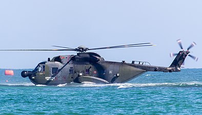 Sikorsky HH-3 on water
-
 Schweizer 300 with inflatable floats
For take-off a step and planing bottom are required to lift from the floating position to planing on the surface. For landing a cleaving action is required to reduce the impact with the surface of the water. A vee bottom parts the water and chines deflect the spray to prevent it damaging vulnerable parts of the aircraft. Additional spray control may be needed using spray strips or inverted gutters. A step is added to the hull, just behind the center of gravity, to stop water clinging to the afterbody so the aircraft can accelerate to flying speed. The step allows air, known as ventilation air, to break the water suction on the afterbody. Two steps were used on the Kawanishi H8K. A step increases the drag in flight. The drag contribution from the step can be reduced with a fairing. A faired step was introduced on the Short Sunderland III.
One goal of seaplane designers was the development of an open ocean seaplane capable of routine operation from very rough water. This led to changes in seaplane hull configuration. High length/beam ratio hulls and extended afterbodies improved rough water capabilities. A hull much longer than its width also reduced drag in flight. An experimental development of the Martin Marlin, the Martin M-270, was tested with a new hull with a greater length/beam ratio of 15 obtained by adding 6 feet to both the nose and tail. Rough-sea capability can be improved with lower take-off and landing speeds because impacts with waves are reduced. The Shin Meiwa US-1A is a STOL amphibian with blown flaps and all control surfaces. The ability to land and take-off at relatively low speeds of about 45 knots and the hydrodynamic features of the hull, long length/beam ratio and inverted spray gutter for example, allow operation in wave heights of 15 feet. The inverted gutters channel spray to the rear of the propeller discs.
Low speed maneuvring is necessary between slipways and buoys and take-off and landing areas. Water rudders are used on seaplanes ranging in size from the Republic RC-3 Seabee to the Beriev A-40 Hydro flaps were used on the Martin Marlin and Martin SeaMaster. Hydroflaps, submerged at the rear of the afterbody, act as a speed brake or differentially as a rudder. A fixed fin, known as a skeg, has been used for directional stability. A skeg, was added to the second step on the Kawanishi H8K flying boat hull.
High speed impacts in rough water between the hull and wave flanks may be reduced using hydro-skis which hold the hull out of the water at higher speeds. Hydro skis replace the need for a boat hull and only require a plain fuselage which planes at the rear. Alternatively skis with wheels can be used for land-based aircraft which start and end their flight from a beach or floating barge. Hydro-skis with wheels were demonstrated as an all-purpose landing gear conversion of the Fairchild C-123, known as the Panto-base Stroukoff YC-134. A seaplane designed from the outset with hydro-skis was the Convair F2Y Sea Dart prototype fighter. The skis incorporated small wheels, with a third wheel on the fuselage, for ground handling.
In the 1950s hydro-skis were envisaged as a ditching aid for large piston-engined aircraft. Water-tank tests done using models of the Lockheed Constellation, Douglas DC-4 and Lockheed Neptune concluded that chances of survival and rescue would be greatly enhanced by preventing critical damage associated with ditching.
-
 Short Sunderland V showing step on wing float and faired step on hull
-
 Kawanishi H8K showing two steps on the hull, a skeg at the second step and spray strips under the forebody
-
 Martin SeaMaster showing outline of hydroflaps at rear
-
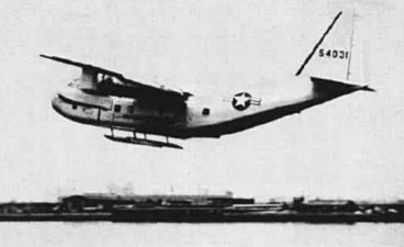 Stroukoff YC-123E showing hydro-skis on pantobase landing gear
-
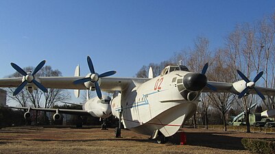 Harbin SH-5 showing deep vee forebody
-
 Shin Meiwa US-1A showing inverted spray gutter from nose to behind propellers
-
 Shin Meiwa US-2 showing revised spray suppressor compared to that on US-1A
-
 Beriev A-40 showing water rudder
-
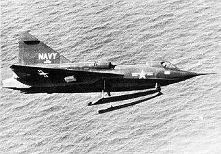 Convair F2Y Sea Dart showing twin hydro-skis
Shipboard operation
The landing gear on fixed-wing aircraft that land on aircraft carriers have a higher sink-rate requirement because the aircraft are flown onto the deck with no landing flare. Other features are related to catapult take-off requirements for specific aircraft. For example, the Blackburn Buccaneer was pulled down onto its tail-skid to set the required nose-up attitude. The naval McDonnell Douglas F-4 Phantom II in UK service needed an extending nosewheel leg to set the wing attitude at launch.
The landing gear for an aircraft using a ski-jump on take-off is subjected to loads of 0.5g which also last for much longer than a landing impact.
Helicopters may have a deck-lock harpoon to anchor them to the deck.
In-flight use
Some aircraft have a requirement to use the landing-gear as a speed brake.
Flexible mounting of the stowed main landing-gear bogies on the Tupolev Tu-22R raised the aircraft flutter speed to 550 kn (1,020 km/h). The bogies oscillated within the nacelle under the control of dampers and springs as an anti-flutter device.
Gear common to different aircraft
Some experimental aircraft have used gear from existing aircraft to reduce program costs. The Martin-Marietta X-24 lifting body used the nose/main gear from the North American T-39 / Northrop T-38 and the Grumman X-29 from the Northrop F-5 / General Dynamics F-16.
Other types
Skis

When an airplane needs to land on surfaces covered by snow, the landing gear usually consists of skis or a combination of wheels and skis.
Detachable

Some aircraft use wheels for takeoff and jettison them when airborne for improved streamlining without the complexity, weight and space requirements of a retraction mechanism. The wheels are sometimes mounted onto axles that are part of a separate "dolly" (for main wheels only) or "trolley" (for a three-wheel set with a nosewheel) chassis. Landing is done on skids or similar simple devices (fixed or retractable). The SNCASE Baroudeur used this arrangement.
Historical examples include the "dolly"-using Messerschmitt Me 163 Komet rocket fighter, the Messerschmitt Me 321 Gigant troop glider, and the first eight "trolley"-using prototypes of the Arado Ar 234 jet reconnaissance bomber. The main disadvantage to using the takeoff dolly/trolley and landing skid(s) system on German World War II aircraft—intended for a sizable number of late-war German jet and rocket-powered military aircraft designs—was that aircraft would likely be scattered all over a military airfield after they had landed from a mission, and would be unable to taxi on their own to an appropriately hidden "dispersal" location, which could easily leave them vulnerable to being shot up by attacking Allied fighters. A related contemporary example are the wingtip support wheels ("pogos") on the Lockheed U-2 reconnaissance aircraft, which fall away after take-off and drop to earth; the aircraft then relies on titanium skids on the wingtips for landing.
Rearwards and sideways retraction

Some main landing gear struts on World War II aircraft, in order to allow a single-leg main gear to more efficiently store the wheel within either the wing or an engine nacelle, rotated the single gear strut through a 90° angle during the rearwards-retraction sequence to allow the main wheel to rest "flat" above the lower end of the main gear strut, or flush within the wing or engine nacelles, when fully retracted. Examples are the Curtiss P-40, Vought F4U Corsair, Grumman F6F Hellcat, Messerschmitt Me 210 and Junkers Ju 88. The Aero Commander family of twin-engined business aircraft also shares this feature on the main gears, which retract aft into the ends of the engine nacelles. The rearward-retracting nosewheel strut on the Heinkel He 219 and the forward-retracting nose gear strut on the later Cessna Skymaster similarly rotated 90 degrees as they retracted.
On most World War II single-engined fighter aircraft (and even one German heavy bomber design) with sideways retracting main gear, the main gear that retracted into the wings was raked forward in the "down" position for better ground handling, with a retracted position that placed the main wheels at some distance aft of their position when downairframe—this led to a complex angular geometry for setting up the "pintle" angles at the top ends of the struts for the retraction mechanism's axis of rotation. with some aircraft, like the P-47 Thunderbolt and Grumman Bearcat, even mandating that the main gear struts lengthened as they were extended to give sufficient ground clearance for their large four-bladed propellers. One exception to the need for this complexity in many WW II fighter aircraft was Japan's famous Zero fighter, whose main gear stayed at a perpendicular angle to the centerline of the aircraft when extended, as seen from the side.
Variable axial position of main wheels
The main wheels on the Vought F7U Cutlass could move 20 inches between a forward and aft position. The forward position was used for take-off to give a longer lever-arm for pitch control and greater nose-up attitude. The aft position was used to reduce landing bounce and reduce risk of tip-back during ground handling.
Tandem layout
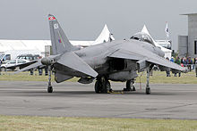
The tandem or bicycle layout is used on the Hawker Siddeley Harrier, which has two main-wheels behind a single nose-wheel under the fuselage and a smaller wheel near the tip of each wing. On second generation Harriers, the wing is extended past the outrigger wheels to allow greater wing-mounted munition loads to be carried, or to permit wing-tip extensions to be bolted on for ferry flights.
A tandem layout was evaluated by Martin using a specially-modified Martin B-26 Marauder (the XB-26H) to evaluate its use on Martin's first jet bomber, the Martin XB-48. This configuration proved so manoeuvrable that it was also selected for the B-47 Stratojet. It was also used on the U-2, Myasishchev M-4, Yakovlev Yak-25, Yak-28 and Sud Aviation Vautour. A variation of the multi tandem layout is also used on the B-52 Stratofortress which has four main wheel bogies (two forward and two aft) underneath the fuselage and a small outrigger wheel supporting each wing-tip. The B-52's landing gear is also unique in that all four pairs of main wheels can be steered. This allows the landing gear to line up with the runway and thus makes crosswind landings easier (using a technique called crab landing). Since tandem aircraft cannot rotate for takeoff, the forward gear must be long enough to give the wings the correct angle of attack during takeoff. During landing, the forward gear must not touch the runway first, otherwise the rear gear will slam down and may cause the aircraft to bounce and become airborne again.
Crosswind landing accommodation

One very early undercarriage incorporating castoring for crosswind landings was pioneered on the Bleriot VIII design of 1908. It was later used in the much more famous Blériot XI Channel-crossing aircraft of 1909 and also copied in the earliest examples of the Etrich Taube. In this arrangement the main landing gear's shock absorption was taken up by a vertically sliding bungee cord-sprung upper member. The vertical post along which the upper member slid to take landing shocks also had its lower end as the rotation point for the forward end of the main wheel's suspension fork, allowing the main gear to pivot on moderate crosswind landings.
Manually-adjusted main-gear units on the B-52 can be set for crosswind take-offs. It rarely has to be used from SAC-designated airfields which have major runways in the predominant strongest wind direction. The Lockheed C-5 Galaxy has swivelling 6-wheel main units for crosswind landings and castoring rear units to prevent tire scrubbing on tight turns.
"Kneeling" gear
Both the nosegear and the wing-mounted main landing gear of the World War II German Arado Ar 232 cargo/transport aircraft were designed to kneel. This made it easier to load and unload cargo, and improved taxiing over ditches and on soft ground.
Some early U.S. Navy jet fighters were equipped with "kneeling" nose gear consisting of small steerable auxiliary wheels on short struts located forward of the primary nose gear, allowing the aircraft to be taxied tail-high with the primary nose gear retracted. This feature was intended to enhance safety aboard aircraft carriers by redirecting the hot exhaust blast upwards, and to reduce hangar space requirements by enabling the aircraft to park with its nose underneath the tail of a similarly equipped jet. Kneeling gear was used on the North American FJ-1 Fury and on early versions of the McDonnell F2H Banshee, but was found to be of little use operationally, and was omitted from later Navy fighters.
The nosewheel on the Lockheed C-5, partially retracts against a bumper to assist in loading and unloading of cargo using ramps through the forward, "tilt-up" hinged fuselage nose while stationary on the ground. The aircraft also tilts backwards. The Messier twin-wheel main units fitted to the Transall and other cargo aircraft can tilt forward or backward as necessary.
The Boeing AH-64 Apache helicopter is able to kneel to fit inside the cargo hold of a transport aircraft and for storage.
Tail support
Aircraft landing gear includes devices to prevent fuselage contact with the ground by tipping back when the aircraft is being loaded. Some commercial aircraft have used tail props when parked at the gate. The Douglas C-54 had a critical CG location which required a ground handling strut. The Lockheed C-130 and Boeing C-17 Globemaster III use ramp supports.

The unladen CG of the rear-engined Ilyushin IL-62 is aft of the main gear due to design decisions stemming from efforts to reduce overall weight, systems complexity and drag; to prevent the fuselage from tilting back when unloaded, the aircraft has a unique fully retractable vertical tail strut with castering wheels to allow towing or pushback. The strut is not intended for taxiing or flight, when the weight of the crew, passengers, cargo and fuel provide the necessary fore-aft balance.
Monowheel

To minimize drag, modern gliders usually have a single wheel, retractable or fixed, centered under the fuselage, which is referred to as monowheel gear or monowheel landing gear. Monowheel gear is also used on some powered aircraft, where drag reduction is a priority, such as the Europa Classic. Much like the Me 163 rocket fighter, some gliders from prior to the Second World War used a take-off dolly that was jettisoned on take-off; these gliders then landed on a fixed skid. This configuration is necessarily accompanied with a taildragger.
Helicopters
Light helicopters use simple landing skids to save weight and cost. The skids may have attachment points for wheels so that they can be moved for short distances on the ground. Skids are impractical for helicopters weighing more than four tons. Some high-speed machines have retractable wheels, but most use fixed wheels for their robustness, and to avoid the need for a retraction mechanism.
Tailsitter
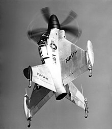
Experimental tailsitter aircraft use landing gear located in their tails for VTOL operation.
Light aircraft
For light aircraft a type of landing gear which is economical to produce is a simple wooden arch laminated from ash, as used on some homebuilt aircraft. A similar arched gear is often formed from spring steel. The Cessna Airmaster was among the first aircraft to use spring steel landing gear. The main advantage of such gear is that no other shock-absorbing device is needed; the deflecting leaf provides the shock absorption.
Folding gear
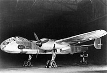
The limited space available to stow landing gear has led to many complex retraction mechanisms, each unique to a particular aircraft. An early example, the German Bomber B combat aircraft design competition winner, the Junkers Ju 288, had a complex "folding" main landing gear unlike any other aircraft designed by either Axis or Allied sides in the war: its single oleo strut was only attached to the lower end of its Y-form main retraction struts, handling the twinned main gear wheels, and folding by swiveling downwards and aftwards during retraction to "fold" the maingear's length to shorten it for stowage in the engine nacelle it was mounted in. However, the single pivot-point design also led to numerous incidents of collapsed maingear units for its prototype airframes.
Tracked
Increased contact area can be obtained with very large wheels, many smaller wheels or track-type gear. Tracked gear made by Dowty was fitted to a Westland Lysander in 1938 for taxi tests, then a Fairchild Cornell and a Douglas Boston. Bonmartini, in Italy, fitted tracked gear to a Piper Cub in 1951. Track-type gear was also tested using a C-47, C-82 and B-50. A much heavier aircraft, an XB-36, was made available for further tests, although there was no intention of using it on production aircraft. The stress on the runway was reduced to one third that of the B-36 four-wheel bogie.

Ground carriage
Ground carriage is a long-term (after 2030) concept of flying without landing gear. It is one of many aviation technologies being proposed to reduce greenhouse gas emissions. Leaving the landing gear on the ground reduces weight and drag. Leaving it behind after take-off was done for a different reason, i.e. with military objectives, during World War II using the "dolly" and "trolley" arrangements of the German Me 163B rocket fighter and Arado Ar 234A prototype jet recon-bomber.
Steering
There are several types of steering. Taildragger aircraft may be steered by rudder alone (depending upon the prop wash produced by the aircraft to turn it) with a freely pivoting tail wheel, or by a steering linkage with the tail wheel, or by differential braking (the use of independent brakes on opposite sides of the aircraft to turn the aircraft by slowing one side more sharply than the other). Aircraft with tricycle landing gear usually have a steering linkage with the nosewheel (especially in large aircraft), but some allow the nosewheel to pivot freely and use differential braking and/or the rudder to steer the aircraft, like the Cirrus SR22.
Some aircraft require that the pilot steer by using rudder pedals; others allow steering with the yoke or control stick. Some allow both. Still others have a separate control, called a tiller, used for steering on the ground exclusively.
Rudder
When an aircraft is steered on the ground exclusively using the rudder, it needs a substantial airflow past the rudder, which can be generated either by the forward motion of the aircraft or by propeller slipstream. Rudder steering requires considerable practice to use effectively. Although it needs airflow past the rudder, it has the advantage of not needing any friction with the ground, which makes it useful for aircraft on water, snow or ice.
Direct

Some aircraft link the yoke, control stick, or rudder directly to the wheel used for steering. Manipulating these controls turns the steering wheel (the nose wheel for tricycle landing gear, and the tail wheel for taildraggers). The connection may be a firm one in which any movement of the controls turns the steering wheel (and vice versa), or it may be a soft one in which a spring-like mechanism twists the steering wheel but does not force it to turn. The former provides positive steering but makes it easier to skid the steering wheel; the latter provides softer steering (making it easy to overcontrol) but reduces the probability of skidding. Aircraft with retractable gear may disable the steering mechanism wholly or partially when the gear is retracted.
Differential braking
Differential braking depends on asymmetric application of the brakes on the main gear wheels to turn the aircraft. For this, the aircraft must be equipped with separate controls for the right and left brakes (usually on the rudder pedals). The nose or tail wheel usually is not equipped with brakes. Differential braking requires considerable skill. In aircraft with several methods of steering that include differential braking, differential braking may be avoided because of the wear it puts on the braking mechanisms. Differential braking has the advantage of being largely independent of any movement or skidding of the nose or tailwheel.
Tiller
A tiller in an aircraft is a small wheel or lever, sometimes accessible to one pilot and sometimes duplicated for both pilots, that controls the steering of the aircraft while it is on the ground. The tiller may be designed to work in combination with other controls such as the rudder or yoke. In large airliners, for example, the tiller is often used as the sole means of steering during taxi, and then the rudder is used to steer during takeoff and landing, so that both aerodynamic control surfaces and the landing gear can be controlled simultaneously when the aircraft is moving at aerodynamic speeds.
Tires and wheels

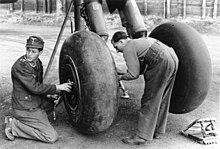
The specified selection criterion, e.g., minimum size, weight, or pressure, are used to select suitable tires and wheels from manufacturer's catalog and industry standards found in the Aircraft Yearbook published by the Tire and Rim Association, Inc.
Gear loading
The choice of the main wheel tires is made on the basis of the static loading case. The total main gear load is calculated assuming that the aircraft is taxiing at low speed without braking:
where is the weight of the aircraft and and are the distance measured from the aircraft's center of gravity(cg) to the main and nose gear, respectively.
The choice of the nose wheel tires is based on the nose wheel load during braking at maximum effort:
where is the lift, is the drag, is the thrust, and is the height of aircraft cg from the static groundline. Typical values for on dry concrete vary from 0.35 for a simple brake system to 0.45 for an automatic brake pressure control system. As both and are positive, the maximum nose gear load occurs at low speed. Reverse thrust decreases the nose gear load, and hence the condition results in the maximum value:
To ensure that the rated loads will not be exceeded in the static and braking conditions, a seven percent safety factor is used in the calculation of the applied loads.
Inflation pressure
Provided that the wheel load and configuration of the landing gear remain unchanged, the weight and volume of the tire will decrease with an increase in inflation pressure. From the flotation standpoint, a decrease in the tire contact area will induce a higher bearing stress on the pavement which may reduce the number of airfields available to the aircraft. Braking will also become less effective due to a reduction in the frictional force between the tires and the ground. In addition, the decrease in the size of the tire, and hence the size of the wheel, could pose a problem if internal brakes are to be fitted inside the wheel rims. The arguments against higher pressure are of such a nature that commercial operators generally prefer the lower pressures in order to maximize tire life and minimize runway stress. To prevent punctures from stones Philippine Airlines had to operate their Hawker Siddeley 748 aircraft with pressures as low as the tire manufacturer would permit. However, too low a pressure can lead to an accident as in the Nigeria Airways Flight 2120.
A rough general rule for required tire pressure is given by the manufacturer in their catalog. Goodyear for example advises the pressure to be 4% higher than required for a given weight or as fraction of the rated static load and inflation.
Tires of many commercial aircraft are required to be filled with nitrogen, and not subsequently diluted with more than 5% oxygen, to prevent auto-ignition of the gas which may result from overheating brakes producing volatile vapors from the tire lining.
Naval aircraft use different pressures when operating from a carrier and ashore. For example, the Northrop Grumman E-2 Hawkeye tire pressures are 260 psi (1.8 MPa) on ship and 210 psi (1.4 MPa) ashore. En-route deflation is used in the Lockheed C-5 Galaxy to suit airfield conditions at the destination but adds excessive complication to the landing gear and wheels
Future developments
Airport community noise is an environmental issue which has brought into focus the contribution of aerodynamic noise from the landing gear. A NASA long-term goal is to confine aircraft objectional noise to within the airport boundary. During the approach to land the landing gear is lowered several miles from touchdown and the landing gear is the dominant airframe noise source, followed by deployed highlift devices. With engines at a reduced power setting on the approach it is necessary to reduce airframe noise to make a significant reduction to total aircraft noise. The addition of add-on fairings is one approach for reducing the noise from the landing gear with a longer term approach to address noise generation during initial design.
Airline specifications require an airliner to reach up to 90,000 take-offs and landings and roll 500,000 km on the ground in its lifetime. Conventional landing gear is designed to absorb the energy of a landing and does not perform well at reducing ground-induced vibrations in the airframe during landing ground roll, taxi and take-off. Airframe vibrations and fatigue damage can be reduced using semi-active oleos which vary damping over a wide range of ground speeds and runway quality.
Accidents
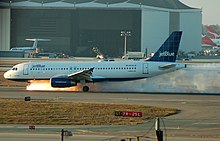

Malfunctions or human errors (or a combination of these) related to retractable landing gear have been the cause of numerous accidents and incidents throughout aviation history. Distraction and preoccupation during the landing sequence played a prominent role in the approximately 100 gear-up landing incidents that occurred each year in the United States between 1998 and 2003. A gear-up landing, also known as a belly landing, is an accident that results from the pilot forgetting to lower the landing gear, or being unable to do so because of a malfunction. Although rarely fatal, a gear-up landing can be very expensive if it causes extensive airframe/engine damage. For propeller-driven aircraft a prop strike may require an engine overhaul.
Some aircraft have a stiffened fuselage underside or added features to minimize structural damage in a wheels-up landing. When the Cessna Skymaster was converted for a military spotting role (the O-2 Skymaster), fiberglass railings were added to the length of the fuselage; they were adequate to support the aircraft without damage if it was landed on a grassy surface.
The Bombardier Dash 8 is notorious for its landing gear problems. There were three incidents involved, all of them involving Scandinavian Airlines, flights SK1209, SK2478, and SK2867. This led to Scandinavian retiring all of its Dash 8s. The cause of these incidents was a locking mechanism that failed to work properly. This also caused concern for the aircraft for many other airlines that found similar problems, Bombardier Aerospace ordered all Dash 8s with 10,000 or more hours to be grounded, it was soon found that 19 Horizon Airlines Dash 8s had locking mechanism problems, so did 8 Austrian Airlines planes, this did cause several hundred flights to be canceled.
On September 21, 2005, JetBlue Airways Flight 292 successfully landed with its nose gear turned 90 degrees sideways, resulting in a shower of sparks and flame after touchdown.
On November 1, 2011, LOT Polish Airlines Flight LO16 successfully belly landed at Warsaw Chopin Airport due to technical failures; all 231 people on board escaped without injury.
Emergency extension systems
In the event of a failure of the aircraft's landing gear extension mechanism a backup is provided. This may be an alternate hydraulic system, a hand-crank, compressed air (nitrogen), pyrotechnic or free-fall system.
A free-fall or gravity drop system uses gravity to deploy the landing gear into the down and locked position. To accomplish this the pilot activates a switch or mechanical handle in the cockpit, which releases the up-lock. Gravity then pulls the landing gear down and deploys it. Once in position the landing gear is mechanically locked and safe to use for landing.
Ground resonance in rotorcraft
Main article: Ground resonanceRotorcraft with fully articulated rotors may experience a dangerous and self-perpetuating phenomenon known as ground resonance, in which the unbalanced rotor system vibrates at a frequency coinciding with the natural frequency of the airframe, causing the entire aircraft to violently shake or wobble in contact with the ground. Ground resonance occurs when shock is continuously transmitted to the turning rotors through the landing gear, causing the angles between the rotor blades to become uneven; this is typically triggered if the aircraft touches the ground with forward or lateral motion, or touches down on one corner of the landing gear due to sloping ground or the craft's flight attitude. The resulting violent oscillations may cause the rotors or other parts to catastrophically fail, detach, and/or strike other parts of the airframe; this can destroy the aircraft in seconds and critically endanger persons unless the pilot immediately initiates a takeoff or closes the throttle and reduces rotor pitch. Ground resonance was cited in 34 National Transportation Safety Board incident and accident reports in the United States between 1990 and 2008.
Rotorcraft with fully articulated rotors typically have shock-absorbing landing gear designed to prevent ground resonance; however, poor landing gear maintenance and improperly inflated tires may contribute to the phenomenon. Helicopters with skid-type landing gear are less prone to ground resonance than those with wheels.
Stowaways
Main article: List of wheel-well stowaway flightsUnauthorized passengers have been known to stowaway on larger aircraft by climbing a landing gear strut and riding in the compartment meant for the wheels. There are extreme dangers to this practice, with numerous deaths reported. Dangers include a lack of oxygen at high altitude, temperatures well below freezing, crush injury or death from the gear retracting into its confined space, and falling out of the compartment during takeoff or landing.
Spacecraft
Launch vehicles


Landing gear has traditionally not been used on the vast majority of launch vehicles, which take off vertically and are destroyed on falling back to earth. With some exceptions for suborbital vertical-landing vehicles (e.g., the Masten Xoie or Armadillo Aerospace's Lunar Lander Challenge vehicle), or for spaceplanes that use the vertical takeoff, horizontal landing (VTHL) approach (e.g., the Space Shuttle orbiter, or the USAF X-37), landing gear have been largely absent from orbital vehicles during the early decades since the advent of spaceflight technology, when orbital space transport has been the exclusive preserve of national-monopoly governmental space programs. Each spaceflight system through 2015 had relied on expendable boosters to begin each ascent to orbital velocity.
Advances during the 2010s in private space transport, where new competition to governmental space initiatives has emerged, have included the explicit design of landing gear into orbital booster rockets. SpaceX has initiated and funded a multimillion-dollar reusable launch system development program to pursue this objective. As part of this program, SpaceX built, and flew eight times in 2012–2013, a first-generation test vehicle called Grasshopper with a large fixed landing gear in order to test low-altitude vehicle dynamics and control for vertical landings of a near-empty orbital first stage. A second-generation test vehicle called F9R Dev1 was built with extensible landing gear. The prototype was flown four times—with all landing attempts successful—in 2014 for low-altitude tests before being self-destructed for safety reasons on a fifth test flight due to a blocked engine sensor port.
The orbital-flight version of the test vehicles–Falcon 9 and Falcon Heavy—includes a lightweight, deployable landing gear for the booster stage: a nested, telescoping piston on an A-frame. The total span of the four carbon fiber/aluminum extensible landing legs is approximately 18 metres (60 ft), and weigh less than 2,100 kilograms (4,600 lb); the deployment system uses high-pressure helium as the working fluid. The first test of the extensible landing gear was successfully accomplished in April 2014 on a Falcon 9 returning from an orbital launch and was the first successful controlled ocean soft touchdown of a liquid-rocket-engine orbital booster. After a single successful booster recovery in 2015, and several in 2016, the recovery of SpaceX booster stages became routine by 2017. Landing legs had become an ordinary operational part of orbital spaceflight launch vehicles.
The newest launch vehicle under development at SpaceX—the Starship—is expected to have landing legs on its first stage called Super Heavy like Falcon 9 but also has landing legs on its reusable second stage, a first for launch vehicle second stages. The first prototype of Starship—Starhopper, built in early 2019—had three fixed landing legs with replaceable shock absorbers. In order to reduce mass of the flight vehicle and the payload penalty for a reusable design, the long-term plan is for Super Heavy to land directly back at the launch site on special ground equipment that is part of the launch mount.
Landers
Spacecraft designed to land safely on extraterrestrial bodies such as the Moon or Mars are known as either legged landers (for example the Apollo Lunar Module) or pod landers (for example Mars Pathfinder) depending on their landing gear. Pod landers are designed to land in any orientation after which they may bounce and roll before coming to rest at which time they have to be given the correct orientation to function. The whole vehicle is enclosed in crushable material or airbags for the impacts and may have opening petals to right it.
Features for landing and movement on the surface were combined in the landing gear for the Mars Science Laboratory.
For landing on low-gravity bodies landing gear may include hold-down thrusters, harpoon anchors and foot-pad screws, all of which were incorporated in the design of comet-lander Philae for redundancy.
In the case of Philae, however, both harpoons and the hold-down thruster failed, resulting in the craft bouncing before landing for good at a non-optimal orientation.
-
Apollo Lunar Module showing landing gear legs
-
 The Mars Pathfinder lander during a ground test encased in its cluster of air bags
-
 Comet lander Philae showing anchoring harpoons (2) and foot-pad screws (3)
-
 Mars Science Laboratory showing rover's wheels which acted as landing gear for initial touchdown
-
 Mars Pathfinder showing one of three petals and deflated airbags
See also
- Dayton-Wright RB-1 Racer, an early example of an airplane with retractable landing gear.
- Landing gear extender
- Tundra tire, a low-pressure landing gear tire allowing landings on rough surfaces
- Undercarriage arrangements of jetliners and other aircraft.
- Verville Racer Aircraft, an early example of an airplane with retractable landing gear.
References
- The Design Of The Aeroplane, Darrol Stinton 1983, ISBN 0-632-01877-1, p. 63
- Wragg, David W. (1973). A Dictionary of Aviation (first ed.). Osprey. p. 269. ISBN 9780850451634.
- "Landing gear". Aviation Dictionary. Retrieved 30 November 2023.
- Farnborough and the Fleet Air Arm, Geoffrey Cooper 2008, ISBN 978 1 85780 306 8, pp. 197–205
- Power The Pratt and Whitney Canada Story, Kenneth H. Sullivan and Larry Milberry 1989, ISBN 0-921022-01-8, pp. 193/194
- Magnesium Overcast The Story of the Convair B-36, Dennis R. Jenkins 2001–2002, ISBN 978-1-58007-129-1, p. 17
- Gerd Roloff (April 2002). "Aircraft Landing Gear" (PDF). Airbus-Deutschland GmbH. The Evolution of a System. Archived from the original (PDF) on 22 November 2008. Retrieved 23 May 2017.
- Article title Archived 2021-03-10 at the Wayback Machine TABLE 1
- Hoerner, Dr.-Ing. Sighard F. (1965). "Fluid-Dynamic Drag: Practical Information on Aerodynamic Drag and Hydrodynamic Resistance" (PDF).
- Raymer, Daniel (30 September 2018). Aircraft Design: A Conceptual Approach, Sixth Edition. AIAA. p. 230. doi:10.2514/4.104909. ISBN 978-1-62410-490-9. S2CID 114292835. Retrieved 6 November 2022.
- "Aviation Week 1950-09-11". 11 September 1950 – via Internet Archive.
- AMT Airframe Handbook Volume 2 (FAA-H-8083-31). Washington DC: FAA. pp. 13–24.
- 747 Creating The World's First Jumbo Jet And Other Adventures From A Life In Aviation, Joe Sutter 2006, ISBN 0 06 088241 7, p. 129
- Sengfelder, Günther (1993). German Aircraft Landing Gear. Atglen, PA USA: Schiffer Publishing. pp. 40–42. ISBN 0-88740-470-7.
A significant advantage of this aircraft was its rough-field landing gear. With the landing gear in the compressed position, the eleven pairs of wheels mounted on independently-sprung legs beneath the fuselage, together with the wide-track main landing gear (8.4 meter, 27 ft 6 in wheel track) and the levered-suspension nose wheel, gave the aircraft outstanding rough field capabilities.
- Magnesium Overcast The Story of the Convair B-36, Dennis R. Jenkins 2001-2002, ISBN 1 58007 042 6, pp. 14/15
- Egbert Torenbeek (1976), Synthesis of Subsonic Airplane Design, Delft University Press, Fig. 10-5
- Airbus A340 And A330, Guy Norris and Mark Wagner 2001, ISBN 0 7603 0889 6, p.29
- Civil Aircraft In Colour, Hiroshi Seo 1984, ISBN 0 7106 0346 0, p. 11
- Airbus A380 Superjumbo Of The 21 St Century, Guy Norris ans Mark Wagner 2010, ISBN 978 0 7603 3838 4, p. 135
- Tarantola, Andrew (6 June 2013). "The World's Largest Cargo Plane Can Swallow a 737 Whole". gizmodo.com.
- "A321 aircraft characteristics" (PDF). Airbus. April 2020. Archived from the original (PDF) on 27 March 2019. Retrieved 24 November 2020.
- "A350 aircraft characteristics" (PDF). Airbus. May 2020. Archived from the original (PDF) on 31 May 2019. Retrieved 24 November 2020.
- "svenska flygmotor | combat biplane | viggen | 1967 | 0650 | Flight Archive". flightglobal.com. 1967. Retrieved 22 November 2019.
- "de havilland | 1961 | 0430 | Flight Archive".
- Havens, Robert F. (1 April 1945). Tank tests of a flying-boat model equipped with several types of fairing designed to reduce the air drag of the main step (PDF) (Report) – via ntrs.nasa.gov.
- Ferguson, J. A.; Seibels, R. E.; Corber, R. J. (1 September 1949). Flight tests of the hydrodynamic characteristics of a Japanese "Emily" flying boat (Report) – via ntrs.nasa.gov.
- Bibliography and review of information relating to the hydrodynamics of seaplanes (PDF) (Report). NASA. 1 September 1945. p. 25. Retrieved 6 November 2022.
- Pepper, P.A.; Kaplan, L. (23 December 1966). "Survey on Seaplane Hydro-Ski Technology" (PDF). Department of the Navy. Archived from the original (PDF) on 29 January 2020. Retrieved 10 March 2022.
- ^ "Aviation Week 1952-06-23". 23 June 1952 – via Internet Archive.
- Brown, David R. Is There A Role For Modern Day Seaplanes in Open Ocean Search and Rescue (Report). p. 35. Retrieved 6 November 2022.
- Use of Seaplanes and Integration within a Sea Base (PDF) (Report). Naval Surface Warfare Center Carderock Division. September 2004. p. 13. Retrieved 6 November 2022.
- Odedra, Jessaji; Hope, Geoff; Kennell, Colen (September 2004). "Use of Seaplanes and Integration within a Sea Base". Defense Technical Information Center.
- Goebel, Greg (1 April 2021). "Beriev A-40, Be-200, & Be-103 Flying Boats". airvectors.net. Archived from the original on 22 January 2022. Retrieved 5 February 2022.
- Feuerbach, Theodore (1951). The effect of hydroflaps on the pitching and braking of flying boats (Report). p. 4. Retrieved 6 November 2022.
- Flight tests of the hydrodynamic characteristics of a Japanese "Emily" flying boat (PDF) (Report). NASA. 1 September 1949. p. Figure 3(d). Retrieved 6 November 2022.
- "Aircraft landing gear".
- Sherman, Frederick S. (September 1956). Symposium on Naval Hydrodynamics. p. 189. doi:10.5962/bhl.title.38156.
- Fisher, Lloyd J. (25 April 1950). Model ditching investigations of three airplanes equipped with hydro-skis (Report) – via ntrs.nasa.gov.
- "1971 | 0062 | Flight Archive".
- "Ski Jump Harrier". Flight International. 4 December 1976. pp. 1630–1635.
- "New life for lynx". Flightglobal.com. 16 July 2002.
- Tupolev Tu-22 Blinder, Sergey Burdin & Alan E Dawes2006, ISBN 1 84415 241 3, p.71
- The X-Planes X-1 To X-31, Jay Miller 1988, ISBN 0 517 56749 0, p.169 and 190
- Canada Aviation and Space Museum (n.d.). "Messerschmitt Me 163B-1a Komet". Archived from the original on 18 February 2009. Retrieved 13 May 2012.
- "Aerostories: Arado 234, July - August 1944: no ordinary missions." Aerostories. Retrieved: 16 March 2016.
- Sengfelder, Günther (1993). German Aircraft Landing Gear. Atglen, PA USA: Schiffer Publishing. pp. 141–142. ISBN 0-88740-470-7.
During retraction the nosewheel had to turn through 90 degrees, which was achieved by means of a mechanism in the head of the wheel fork. On retraction, a spring-loaded level with pulley, which limited deflection to 60 degrees by means of a locking hook and stop, was folded into the fuselage and turned through ninety degrees after making contact with a guide.
- U.S. Naval Air Superiority Development Of Shipborne Jet Fighters 1943–1962, Tommy H. Thomason 2007, ISBN 978 1 58007 110 9, pp. 106/107
- Dow, Andrew (2015). Pegasus: The Heart of the Harrier (2 ed.). Pen and Sword. p. 312. ISBN 978-1-84884-042-3.
- Air Force Legends Number 201 The Martin XB-51, Scott Libis, 1998, ISBN 0 942612 00 0, p. 2
- The B-47. Lookout Mountain Air Force Station. 1950.
- Flying American Combat Aircraft The Cold War, Edited by Robin Higham 2005, ISBN 978 0 8117 3238 3, p. 32
- Niu, Michael Chun-Yung (1998). Airframe Structural Design (PDF). Conmilit Press Ltd. p. 436. ISBN 962-7128-04-X. Archived from the original (PDF) on 11 July 2011.
- Sengfelder, Günther (1993). German Aircraft Landing Gear. Atglen, PA: Schiffer Publishing. pp. 40–42. ISBN 0-88740-470-7.
A significant advantage of this aircraft was its rough-field landing gear. With the landing gear in the compressed position, the eleven pairs of wheels mounted on independently-sprung legs beneath the fuselage, together with the wide-track main landing gear (8.4 meter, 27 ft 6 in wheel track) and the levered-suspension nose wheel, endowed the aircraft with outstanding rough field capabilities.
- "North American NA-141 Fury (FJ-1)". Yanks Air Museum. Archived from the original on 18 December 2015. Retrieved 23 January 2016.
- Mesko, Jim (2002). FH Phantom/F2H Banshee in action. Carrollton, Texas: Squadron/Signal Publications, Inc. p. 12. ISBN 0-89747-444-9.
- Niu, Michael Chun-Yung (1998). Airframe Structural Design (PDF). Conmilit Press Ltd. p. 435. ISBN 962-7128-04-X. Archived from the original (PDF) on 11 July 2011.
- http://everyspec.com/MIL-STD/MIL-STD-1700-1799/MIL-STD-1791C_55770/ FIGURE B-6
- Niu, Michael Chun-Yung (1998). Airframe Structural Design (PDF). Conmilit Press Ltd. pp. 432, 434. ISBN 962-7128-04-X. Archived from the original (PDF) on 11 July 2011.
- Jane's All The World's Aircraft 1982–83, John W.R. Taylor, ISBN 0 7106 0748 2, p. 394
- Landing Gear Integration in Aircraft Conceptual Design (Report). Virginia Polytechnic Institute and State University. September 1996. Retrieved 6 November 2022.
- http://everyspec.com/MIL-SPECS/MIL-SPECS-MIL-L/MIL-L-87139_8546/ p.31
- http://everyspec.com/MIL-STD/MIL-STD-1700-1799/MIL-STD-1791C_55770/ Table III, Figures B-71 and B-95
- Gordon, Yefim; Komissarov, Dmitry; Komissarov, Sergey (2004). OKB Ilyushin: a History of the Design Bureau and its Aircraft. Hinkley, England: Midland Publishing. pp. 255, 270. ISBN 1-85780-187-3.
- "Europa XS Monowheel Overview". Europa Aircraft Ltd. 2011. Archived from the original on 5 December 2008. Retrieved 13 May 2012.
- Cox, Taylor. "Skids or Wheels?". helis.com. Retrieved 3 March 2018.
- "Ju288の脚". www5a.biglobe.ne.jp.
- Sengfelder, Günther (1993). German Aircraft Landing Gear. Atglen, PA: Schiffer Publishing. pp. 175–177. ISBN 0-88740-470-7.
The Ju 288's landing gear was most innovative in its design. A Y-shaped bearer was mounted in the engine nacelle with its upper arms hinged. At the bottom end of this bearer was the shock absorber leg, which was likewise hinged. Two double-brake wheels, with (metric) size 1015 x 380 tires, were mounted on the cross-axle. During the retraction cycle a folding strut was raised by a hydraulic jack. The bottom part of the folding strut drew the Y-bearer upwards. Functioning via a lever-and-gear arrangement, a pushrod positioned parallel to the Y-bearer acted upon another gear segment mounted to the oleo leg's hinge pin and rotated it about this as the Y-bearer was drawn upwards.
- https://www.flightglobal.com/pdfarchive/view/1943/1943 - 2372.html
- https://www.flightglobal.com/pdfarchive/view/1971/1971 - 2630.html
- Magnesium Overcast The Story of the Convair B-36, Dennis R. Jenkins 2001–2002, ISBN 978 1 58007 129 1, p.17
- "History of Aircraft Track Landing Gear". Air Force Materiel Command. 30 July 2019.
- International Air Transport Association (June 2014). "Technology Roadmap" (PDF). iata.org. Archived from the original (PDF) on 14 May 2014. Retrieved 28 February 2022.
- Landing Gear Integration in Aircraft Conceptual Design (PDF) (Report). NASA. 1 March 1997. p. 30. Retrieved 6 November 2022.
- ^ Chai, Sonny T.; Mason, William H. (1996). Landing Gear Integration in Aircraft Conceptual Design (PDF). NASA CR-205551. Vol. MAD 96-09-01 (revised March 1, 1997 ed.). Blacksburg, Virginia: Virginia Polytechnic Institute and State University. OCLC 39005288. Retrieved 25 October 2018 – via NASA.
- "Test Pilot" Tony Blackman, Grub Street Publishing 2009, ISBN 9781906502362, p. 177
- "Goodyear Aviation Technical Resources". Goodyear Tire & Rubber Company. Retrieved 6 November 2022.
- FAA Ruling: Use of Nitrogen or Other Inert Gas for Tire inflation in Lieu of Air, Docket No. 26147 Amendment No. 25-78 RIN 2120-AD87 (Report). 26 February 1993. Retrieved 6 November 2022.
- Jane's All The World's Aircraft 1982–1983, Edited by John W. R. Taylor, ISBN 0 86720 621 7, p. 376
- MIL87139, p. 24
- http://digitool.library.mcgill.ca/webclient/StreamGate?folder_id=0&dvs=1575683504592~592, p. 5
- Powell, Clemans A.; Preisser, John S. (January 2000). NASA's Subsonic Jet Transport Noise Reduction Research (PDF) (Report).
- Dobrzynski, Werner; Chow, Leung Choi; Smith, Malcolm; Boillot, Antoine; Dereure, Olivier; Molin, Nicolas (2010). "Experimental assessment of low noise landing gear component design" (PDF). Aeroacoustics. 9 (6): 763–786. doi:10.1260/1475-472X.9.6.763. S2CID 55847377. Retrieved 6 November 2022.
- The Office of the NASA Aviation Safety Reporting System (January 2004). "Gear Up Checkup" (PDF). Call Back Aviation Safety Reporting System. No. 292. NASA. Retrieved 6 November 2022.
- NTSB Identification: LAX05IA312 (Report). NTSB. Retrieved 6 November 2022.
- Scislowska, Monika (3 November 2011). "Warsaw airport back to work after plane emergency". NBC News. Retrieved 13 January 2012.
- "Boeing 757 Landing Gear". Biggles Software. 29 December 2011. Archived from the original on 24 March 2009. Retrieved 13 May 2012.
- Stellan F. Hilmerby (24 November 2009). "Landing Gear". Stellans Flightsim Pages. Retrieved 13 May 2012.
- ^ Garrison, Peter (December 2008). "How Things Work: Ground Resonance". airspacemag.com. Air and Space Magazine. Retrieved 6 November 2018.
- ^ "Rotorcraft Flying Handbook" (PDF). faa.gov. Federal Aviation Administration. 2000. pp. 11–17. Retrieved 6 November 2018.
- "Wheel-well Stowaways Risk Lethal Levels of Hypoxia and Hypothermia" (PDF). Flight Safety Foundation. May–June 1997. Retrieved 15 June 2015.
- Hanlon, Michael (11 June 2013). "Roll up for the Red Planet". The Telegraph. Archived from the original on 12 June 2013. Retrieved 26 October 2013.
the space race is flaring back into life, and it's not massive institutions such as Nasa that are in the running. The old view that human space flight is so complex, difficult and expensive that only huge government agencies could hope to accomplish it is being disproved by a new breed of flamboyant space privateers, who are planning to send humans out beyond the Earth's orbit for the first time since 1972.
- Foust, Jeff (18 October 2013). "SpaceX wrapping up Falcon 9 second stage investigation as it moves on from Grasshopper". NewSpace Journal. Retrieved 26 October 2013.
- Klotz, Irene (17 October 2013). "SpaceX Retires Grasshopper, New Test Rig To Fly in December". Space News. Archived from the original on 21 October 2013. Retrieved 26 October 2013.
- Foust, Jeff (23 August 2014). "Falcon 9 test vehicle destroyed in accident". NewSpace Journal. Retrieved 23 August 2014.
- Leone, Dan (13 May 2013). "SpaceX Leases Pad in New Mexico for Next Grasshopper Tests". SpaceNews. Archived from the original on 3 September 2013. Retrieved 3 August 2013.
- "Landing Legs". SpaceX News. 29 July 2013. Retrieved 30 July 2013.
The Falcon 9 first stage carries landing legs which will deploy after stage separation and allow for the rocket's soft return to Earth. The four legs are made of state-of-the-art carbon fiber with aluminum honeycomb. Placed symmetrically around the base of the rocket, they stow along the side of the vehicle during liftoff and later extend outward and down for landing.
- "Landing Legs". SpaceX News. 12 April 2013. Retrieved 2 August 2013.
The Falcon Heavy first stage center core and boosters each carry landing legs, which will land each core safely on Earth after takeoff. After the side boosters separate, the center engine in each will burn to control the booster's trajectory safely away from the rocket. The legs will then deploy as the boosters turn back to Earth, landing each softly on the ground. The center core will continue to fire until stage separation, after which its legs will deploy and land it back on Earth as well. The landing legs are made of state-of-the-art carbon fiber with aluminum honeycomb. The four legs stow along the sides of each core during liftoff and later extend outward and down for landing.
- Lindsey, Clark (2 May 2013). "SpaceX shows a leg for the "F-niner"". Archived from the original on 31 October 2014. Retrieved 2 May 2013.
F9R (pronounced F-niner) shows a little leg. Design is a nested, telescoping piston w A frame... High pressure helium. Needs to be ultra light.
- Belfiore, Michael (22 April 2014). "SpaceX Brings a Booster Safely Back to Earth". MIT Technology Review. Retrieved 25 April 2014.
-
Norris, Guy (28 April 2014). "SpaceX Plans For Multiple Reusable Booster Tests". Aviation Week. Retrieved 27 April 2014.
The April 17 F9R Dev 1 flight, which lasted under 1 min., was the first vertical landing test of a production-representative recoverable Falcon 9 v1.1 first stage, while the April 18 cargo flight to the ISS was the first opportunity for SpaceX to evaluate the design of foldable landing legs and upgraded thrusters that control the stage during its initial descent.
- ^ Musk, Elon (1 March 2018). "Making Life Multi-Planetary". New Space. 6 (1): 2–11. Bibcode:2018NewSp...6....2M. doi:10.1089/space.2018.29013.emu.
- Baylor, Michael (2 June 2019). "SpaceX readying Starhopper for hops in Texas as Pad 39A plans materialize in Florida". NASASpaceFlight.com. Retrieved 3 June 2019.
- Ball, Andrew; Garry, James; Lorenz, Ralph; Kerzhanovich, Viktor (2007). Planetary Landers and Entry Probes. Cambridge University Press. p. 72,74,75,147. doi:10.1017/CBO9780511536052. ISBN 978-0-521-82002-8. Retrieved 6 November 2022.
- Ball, Andrew; Garry, James; Lorenz, Ralph; Kerzhanovich, Viktor (2007). Planetary Landers and Entry Probes. Cambridge University Press. p. 76. doi:10.1017/CBO9780511536052. ISBN 978-0-521-82002-8. Retrieved 6 November 2022.
- Ball, Andrew (2007). "26". Planetary Landers and Entry Probe. Cambridge University Press. doi:10.1017/CBO9780511536052. ISBN 978-0-521-82002-8.
- "Problems hit Philae after historic first comet landing". New Scientist. 14 November 2014. Retrieved 6 November 2022.
External links
- "Standard Naming Convention for Aircraft Landing Gear Configurations" (PDF). FAA. 6 October 2005.
- How to change the landing gear of an Airbus A380 (YouTube). Emirates Airline. 28 May 2018. Archived from the original on 8 November 2021.
complete replacement of landing gear systems
- Scholz, Dieter. "Summary: Aircraft Design in a Nutshell" (PDF). Aircraft Design: Lecture Notes. Hamburg, Germany: Hamburg Open Online University (HOOU). pp. 19–20. Retrieved 2 November 2018.
- Al-Hussaini, A.A. (2014–2015). "5: Undercarriage (Landing Gear) Layout Design" (PDF). Aircraft Design. University of Technology, Iraq: Mechanical Department/Aeronautical Branch. Retrieved 14 November 2018.
- "Aircraft Systems: Aircraft Wheels". AeroSavvy. 8 October 2019.
 is calculated assuming that the aircraft is taxiing at low speed without braking:

 is the weight of the aircraft and
  and
and  are the distance measured from the aircraft's
  during braking at maximum effort:

 is the lift,
  is the drag,
  is the thrust, and
  is the height of aircraft cg from the static groundline. Typical values for
  on dry concrete vary from 0.35 for a simple brake system to 0.45 for an automatic brake pressure control system. As both
  results in the maximum value:
