... it is beneath the dignity of excellent men to waste their time in calculation when any peasant could do the work just as accurately with the aid of a machine.
— Gottfried Leibniz
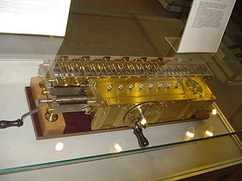
The stepped reckoner or Leibniz calculator was a mechanical calculator invented by the German mathematician Gottfried Wilhelm Leibniz (started in 1673, when he presented a wooden model to the Royal Society of London and completed in 1694). The name comes from the translation of the German term for its operating mechanism, Staffelwalze, meaning "stepped drum". It was the first calculator that could perform all four basic arithmetic operations.
Its intricate precision gearwork, however, was somewhat beyond the fabrication technology of the time; mechanical problems, in addition to a design flaw in the carry mechanism, prevented the machines from working reliably.
Two prototypes were built; today only one survives in the National Library of Lower Saxony (Niedersächsische Landesbibliothek) in Hanover, Germany. Several later replicas are on display, such as the one at the Deutsches Museum, Munich. Despite the mechanical flaws of the stepped reckoner, it suggested possibilities to future calculator builders. The operating mechanism, invented by Leibniz, called the stepped cylinder or Leibniz wheel, was used in many calculating machines for 200 years, and into the 1970s with the Curta hand calculator.
Description
Further information: Leibniz wheel
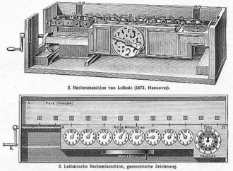
The stepped reckoner was based on a gear mechanism that Leibniz invented and that is now called the Leibniz wheel. It is unclear how many different variants of the calculator were made. Some sources, such as the drawing to the right, show a 12-digit version. This section describes the surviving 16-digit prototype in Hanover.

In the position shown, the counting wheel meshes with 3 of the 9 teeth on the Leibniz wheel
The machine is about 67 cm (26 inches) long, made of polished brass and steel, mounted in an oak case. It consists of two attached parallel parts: an accumulator, which can be thought of as an accumulator register which is found in older processor instruction set architectures, section to the rear, which can hold 16 decimal digits, and an 8-digit input section to the front. The input section has 8 dials with knobs to set the operand number, a telephone-like dial to the right to set the multiplier digit, and a crank on the front to perform the calculation. The result appears in the 16 windows on the rear accumulator section. The input section is mounted on rails and can be moved along the accumulator section with a crank on the left end that turns a worm gear, to change the alignment of operand digits with accumulator digits. There is also a tens-carry indicator and a control to set the machine to zero. The machine can:
- add or subtract an 8-digit number to/from a 16-digit number,
- multiply two 8-digit numbers to get a 16-digit result,
- divide a 16-digit number by an 8-digit divisor.
Addition or subtraction is performed in a single step, with a turn of the crank. Multiplication and division are performed digit by digit on the multiplier or divisor digits, in a procedure equivalent to the familiar long multiplication and long division procedures taught in school. Sequences of these operations can be performed on the number in the accumulator; for example, it can calculate roots by a series of divisions and additions.
History

Leibniz got the idea for a calculating machine in 1672 in Paris, from a pedometer. Later he learned about Blaise Pascal's machine when he read Pascal's Pensées. He concentrated on expanding Pascal's mechanism so it could multiply and divide. He presented a wooden model to the Royal Society of London on 1 February 1673 and received much encouragement. In a letter of 26 March 1673 to Johann Friedrich, where he mentioned the presentation in London, Leibniz described the purpose of the "arithmetic machine" as making calculations "leicht, geschwind, gewiß" , i.e. easy, fast, and reliable. Leibniz also added that theoretically the numbers calculated might be as large as desired, if the size of the machine was adjusted; quote: "eine zahl von einer ganzen Reihe Ziphern, sie sey so lang sie wolle (nach proportion der größe der Machine)" [sic]. In English: "a number consisting of a whole series of figures, as long as it may be (in proportion to the size of the machine)". His first preliminary brass machine was built between 1674 and 1685. His so-called older machine was built between 1686 and 1694. The 'younger machine', the surviving machine, was built from 1690 to 1720.
In 1775 the 'younger machine' was sent to the University of Göttingen for repair, and was forgotten until 1876 when a crew of workmen found it in an attic room of a university building in Göttingen. It was returned to Hanover in 1880. From 1894 to 1896 Artur Burkhardt, founder of a major German calculator company restored it, and it has been kept at the Gottfried Wilhelm Leibniz Library ever since.
Operation
The machine performs multiplication by repeated addition, and division by repeated subtraction. The basic operation performed is to add (or subtract) the operand number to the accumulator register, as many times as desired (to subtract, the operating crank is turned in the opposite direction). The number of additions (or subtractions) is controlled by the multiplier dial. It operates like a telephone dial, with ten holes in its circumference numbered 0–9. To multiply by a single digit, 0–9, a knob-shaped stylus is inserted in the appropriate hole in the dial, and the crank is turned. The multiplier dial turns clockwise, the machine performing one addition for each hole, until the stylus strikes a stop at the top of the dial. The result appears in the accumulator windows. Repeated subtractions are done similarly except the multiplier dial turns in the opposite direction, so a second set of digits, in red, are used. To perform a single addition or subtraction, the multiplier is simply set at one.
To multiply by numbers over 9:
- The multiplicand is set into the operand dials.
- The first (least significant) digit of the multiplier is set into the multiplier dial as above, and the crank is turned, multiplying the operand by that digit and putting the result in the accumulator.
- The input section is shifted one digit to the left with the end crank.
- The next digit of the multiplier is set into the multiplier dial, and the crank is turned again, multiplying the operand by that digit and adding the result to the accumulator.
- The above two steps are repeated for each multiplier digit. At the end, the result appears in the accumulator windows.
In this way, the operand can be multiplied by as large a number as desired, although the result is limited by the capacity of the accumulator.
To divide by a multidigit divisor, this process is used:
- The dividend is set into the accumulator, and the divisor is set into the operand dials.
- The input section is moved with the end crank until the lefthand digits of the two numbers line up.
- The operation crank is turned and the divisor is subtracted from the accumulator repeatedly until the left hand (most significant) digit of the result is 0.if it shows any other number, that is the remainder.. The number showing on the multiplier dial is then the first digit of the quotient.
- The input section is shifted right one digit.
- The above two steps are repeated to get each digit of the quotient, until the input carriage reaches the right end of the accumulator.
It can be seen that these procedures are just mechanized versions of long division and multiplication.
References
- ^ Kidwell, Peggy Aldritch; Williams, Michael R. (1992). The Calculating Machines: Their history and development. MIT Press., pp. 38–42, translated and edited from Martin, Ernst (1925). Die Rechenmaschinen und ihre Entwicklungsgeschichte. Germany: Pappenheim.
- ^ Liebezeit, Jan-Willem (July 2004). "Leibniz Rechenmaschinen". Friedrich Schiller Univ. of Jena.
- Beeson, Michael J. (2004). "The Mechanization of Mathematics". In Teucher, Christof (ed.). Alan Turing: Life and Legacy of a Great Thinker. Springer. p. 82. ISBN 3-540-20020-7.
- Dunne, Paul E. "Mechanical Calculators prior to the 19th Century (Lecture 3)". Course Notes 2PP52:History of Computation. Computer Science Dept., Univ. of Liverpool. Retrieved 2008-01-21.
- ^ Noll, P. (2002-01-27). "Gottfried Wilhelm Leibniz". Verband der Elektrotechnik Electronik Informationstechnic e.V. (Association for Electrical, Electronic and Information Technologies). Archived from the original (PDF) on January 8, 2008. Retrieved 2008-01-21.
- Vegter, Wobbe (2005). "Gottfried Wilhelm von Leibniz". Cyber heroes of the past. hivemind.net. Retrieved 2008-01-21.
External links
- Redshaw, Kerry. "Picture Gallery: Gottfried Wilhelm Leibniz". Pioneers of computing. KerryR personal website. Retrieved 2008-07-06. Pictures of machine and diagrams of mechanism
- "'The Great Humming God'". ChessBase News. Chessbase GmbH, Germany. 2003-04-28. Retrieved 2008-07-06. News article in chess magazine showing closeup pictures of Hanover machine.